EGR Coolers and Oil Coolers are heat exchangers used in various cooling and thermal management systems. They must meet demanding requirements for leak tightness, durability, and heat resistance. Therefore, many manufacturers use vacuum brazing to join metal components.
This technology is suitable for a wide range of applications. Common examples include nickel-based brazing for EGR Coolers, copper brazing for Oil Coolers, and nickel- or copper-based brazing for stainless steel and other compatible materials.
However, each application has its own technical requirements. Manufacturers should therefore select a vacuum brazing furnace based on the base material, brazing filler metal, processing temperature, and actual production capacity.
1. Common Vacuum Brazing Applications
1.1. Nickel-Based Brazing for EGR Coolers
An EGR Cooler is a heat exchanger that cools exhaust gas recirculation gases in an engine. It operates under high-temperature conditions. Therefore, its joints must provide suitable mechanical strength and leak tightness.
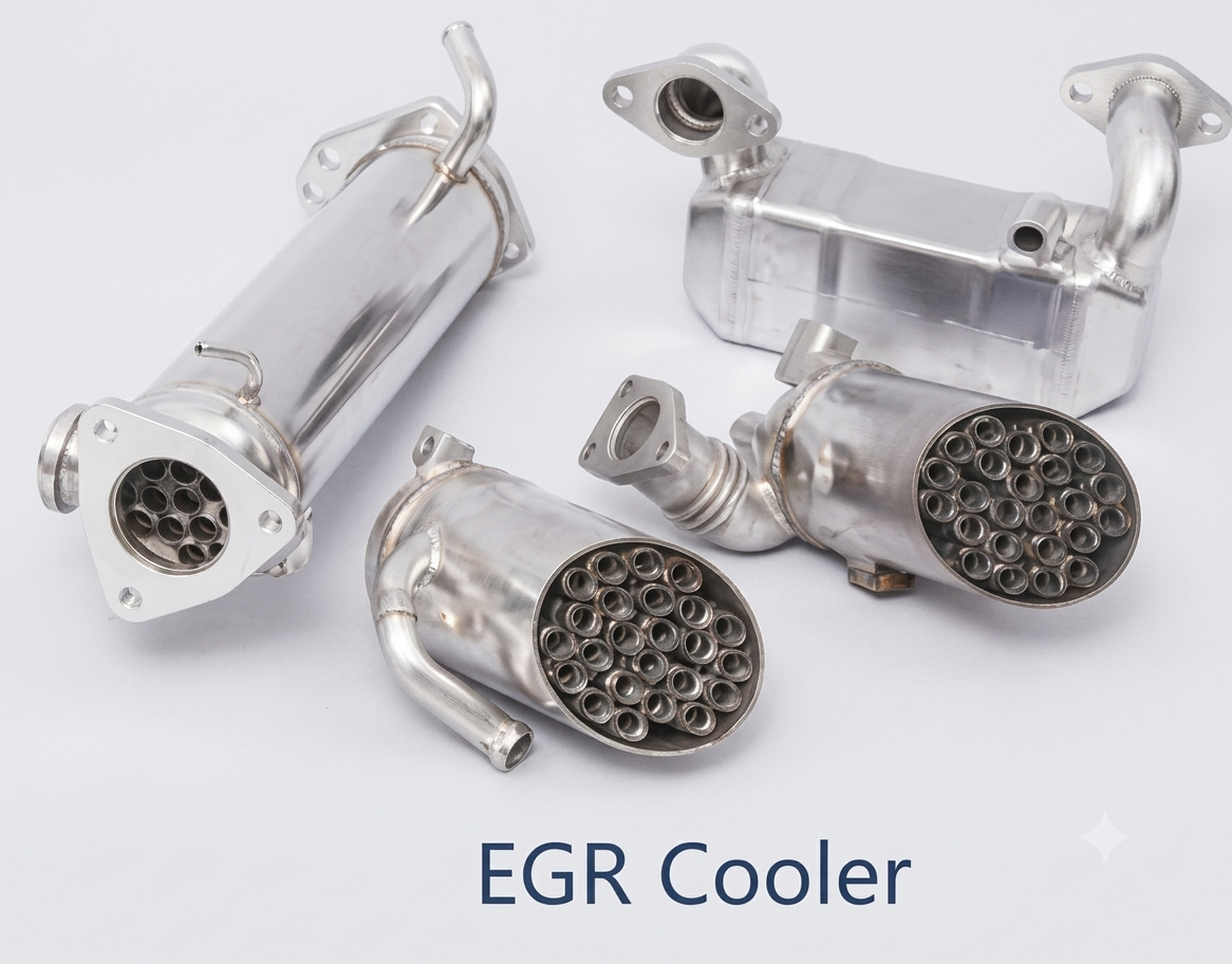
Nickel-based brazing is used in applications where the base materials and process requirements are compatible with this brazing method.
In these applications, manufacturers must carefully control the brazing temperature and holding time. In addition, the vacuum level and temperature uniformity should be evaluated to ensure consistent processing conditions.
1.2. Copper Brazing for Oil Coolers
Oil Coolers regulate oil temperature in engines and industrial systems. Consequently, joint quality directly affects product leak tightness and reliability.
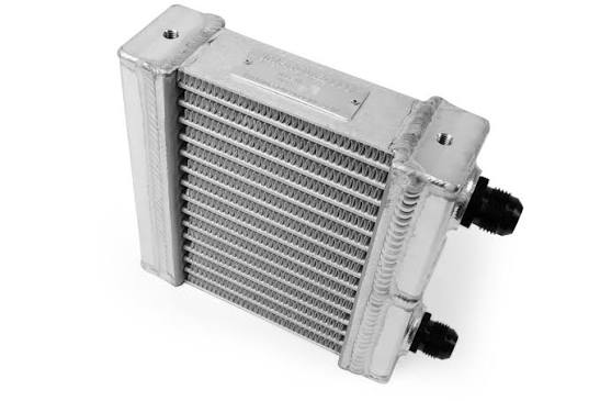
Copper brazing can be used when the base materials and technical requirements are suitable. However, manufacturers should verify the compatibility between the base metal and brazing filler metal before defining the production cycle.
Temperature control is also essential. Proper control helps minimize thermal distortion and maintain consistent joint quality.
1.3. Nickel and Copper Brazing for Stainless Steel and Other Materials
Beyond EGR Coolers and Oil Coolers, vacuum brazing can also be used to join stainless steel and other metal components.
Depending on the application, manufacturers may consider nickel-based or copper-based brazing filler metals. However, the selection must account for the base material composition and the product’s operating conditions.
Manufacturers should also evaluate corrosion resistance, joint strength, and operating temperature. These factors help determine the appropriate filler metal and brazing cycle.
2. Why Use Vacuum Brazing Technology?
During heating, metal surfaces can oxidize when exposed to air. This oxidation may affect filler metal wetting and overall joint quality.
Vacuum brazing takes place in a vacuum environment. As a result, it helps reduce oxygen exposure and provides better control over processing conditions.
Other key benefits include:
- Reduced oxidation: Minimizes exposure to oxygen during heating.
- Multiple-joint brazing: Allows multiple joints to be brazed in a single cycle.
- Temperature control: Enables heating programs to be configured according to technical requirements.
- Complex component processing: Supports assemblies with multiple joints and intricate geometries.
- Batch production capability: Can improve productivity when the furnace configuration is properly selected.
However, final joint quality also depends on the base material, brazing filler metal, and operating conditions. Therefore, manufacturers should evaluate the complete process before investing in equipment.
3. How Does the Vacuum Brazing Process Work?
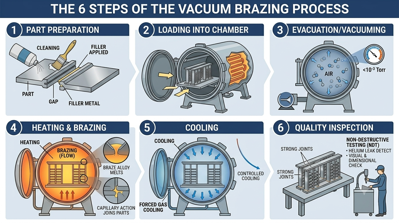
A typical vacuum brazing cycle consists of six basic steps.
Step 1: Product Preparation
First, metal components must be cleaned and assembled according to the product design. The brazing filler metal is then positioned at the joints to be formed.
Step 2: Loading the Furnace
Next, the components are placed in the furnace’s working zone. The loading arrangement must accommodate the product dimensions and fixtures.
Proper spacing is also important. This helps promote more uniform heating throughout the load.
Step 3: Vacuum Pumping
After the furnace chamber is sealed, the vacuum pumping system removes gas from the chamber until the required pressure is reached.
However, the target vacuum level depends on the base material and brazing filler metal. Therefore, the operating parameters should be established according to the actual process requirements.
Step 4: Heating and Brazing
The furnace then follows a programmed heating cycle. Once the appropriate brazing temperature is reached, the filler metal melts and forms a joint between the components.
During this stage, precise temperature and holding-time control are essential. This helps maintain process consistency across production batches.
Step 5: Cooling
After brazing, the components are cooled according to the specified cycle. The cooling method must be suitable for the material and product design.
Cooling time also affects the total cycle time. Therefore, manufacturers should consider this factor when calculating production capacity.
Step 6: Quality Inspection
Finally, the finished components are inspected to evaluate joint quality. Inspection criteria may include visual appearance, dimensional distortion, and leak tightness.
In particular, EGR Coolers and Oil Coolers often require leak testing according to product specifications. This step helps identify defects that could affect product performance and reliability.
4. How to Choose the Right Vacuum Brazing Furnace
Furnace selection should not be based solely on maximum temperature or heating power. Instead, manufacturers should evaluate several technical factors together.
4.1. Identify the Base Material and Brazing Filler Metal
First, identify the product’s base material and the intended brazing filler metal.
- EGR Coolers: Evaluate the requirements for nickel-based brazing.
- Oil Coolers: Confirm the suitability of copper brazing.
- Stainless steel components: Select the filler metal based on material composition and operating requirements.
Next, determine the brazing temperature and holding time. These parameters must be compatible with the material properties.
4.2. Determine Product Dimensions and Production Capacity
The furnace’s working zone must be large enough to accommodate the components and fixtures. However, choosing a larger chamber does not necessarily improve production efficiency.
Manufacturers should therefore consider:
- Product dimensions and weight.
- Number of components per batch.
- Component arrangement inside the furnace.
- Total cycle time.
- Required daily output.
For example, high-volume production requires a balance between batch size, heating time, and cooling time. This helps manufacturers select a furnace configuration that meets their production targets.
4.3. Evaluate Temperature Uniformity
Temperature uniformity affects brazing conditions at different positions within the furnace. Therefore, it is an important criterion when selecting equipment.
Manufacturers should evaluate:
- Operating temperature range.
- Heating rate.
- Temperature uniformity throughout the working zone.
- Holding-time control.
- Temperature stability between production batches.
For components with multiple joints, appropriate temperature control helps maintain consistent processing conditions.
4.4. Select the Appropriate Vacuum System
In addition to the heating chamber, the vacuum system must be selected according to process requirements. Important parameters include target pressure, pumping speed, and pump-down time.
Manufacturers should also consider the system’s ability to maintain the required vacuum conditions throughout the cycle. Gas and vapor loads generated during heating must also be taken into account.
Depending on the system design, the following pumps may be used:
- Rotary Vane Pump: An oil-sealed mechanical vacuum pump.
- Booster Pump: Increases pumping performance within the appropriate pressure range.
- Other vacuum pumps: Selected according to the required vacuum level and operating conditions.
Therefore, pump selection should not be based on motor power alone. The complete vacuum system must be evaluated against the process requirements.
4.5. Consider Cooling Performance and Automation
Cooling time has a significant impact on the total production cycle. Manufacturers should therefore evaluate cooling methods that suit the material and product requirements.
In addition, PLC and HMI systems, together with data-recording functions, can support process monitoring. These features also help improve traceability and control operating parameters across production batches.
5. Vacuum Brazing Furnace Selection Guide by Application
| Application | Key Selection Criteria |
|---|---|
| EGR Cooler – nickel-based brazing | Brazing temperature, vacuum level, and temperature uniformity |
| Oil Cooler – copper brazing | Material compatibility, brazing cycle, and leak tightness |
| Stainless steel – nickel-based brazing | Filler metal properties and processing conditions |
| Stainless steel – copper brazing | Material compatibility and brazing temperature |
| High-volume production | Batch capacity and total cycle time |
| Components requiring high leak tightness | Brazing process control and leak testing |
Overall, no single furnace model is suitable for every application. Manufacturers should select the configuration based on actual product characteristics and technical requirements.
6. Why Is Leak Testing Necessary After Brazing?
For EGR Coolers and Oil Coolers, leak tightness is a critical quality requirement. However, a joint that appears acceptable visually may still contain a small leak path.
Therefore, manufacturers should perform leak testing according to the product’s inspection standards. The test method must be appropriate for the required leak-tightness specification and actual operating conditions.
A typical production workflow may include:
Assembly → Vacuum Brazing → Cooling → Leak Testing → Quality Inspection → Product Finishing
In addition, defining acceptance criteria in advance helps manufacturers maintain consistent quality control.
7. ULVAC Solution: FBC-317C and FBC-418C Continuous Vacuum Brazing Furnaces
The ULVAC FBC-317C and FBC-418C are continuous vacuum brazing furnace models designed for industrial production. Their multi-chamber configuration supports temperature and vacuum control throughout the processing cycle.
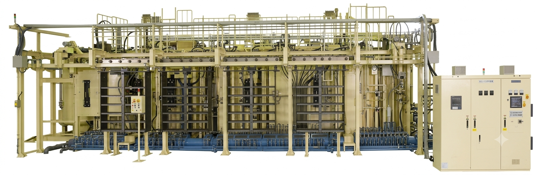
Key features include:
- Load capacity of up to 450 kg: Supports large-scale production requirements.
- Maximum temperature of 1,200°C: Suitable for various vacuum brazing processes.
- Five-zone temperature control: The main brazing chamber achieves temperature uniformity of ±5°C based on a nine-point measurement.
- Vacuum system: Ultimate pressure below 1.0 Pa in the main chambers helps reduce oxidation during processing.
- Multi-chamber design: Integrates preheating, brazing, and cooling stages to support continuous operation.
With these features, ULVAC furnaces can be considered for nickel-based brazing of EGR Coolers, copper brazing of Oil Coolers, and brazing of stainless steel components, subject to material compatibility and actual process requirements.
Conclusion
Selecting a vacuum brazing furnace for EGR Coolers, Oil Coolers, and stainless steel components requires careful evaluation of several factors. Base materials, brazing filler metals, brazing temperature, and vacuum level are among the most important considerations.
Manufacturers should also assess temperature uniformity, batch capacity, and leak-testing requirements. By evaluating these factors together, they can select a system that better matches their actual production needs.
Looking for a vacuum brazing solution for nickel-based EGR Cooler brazing, copper brazing for Oil Coolers, or stainless steel components? Contact ULVAC Vietnam today to discuss your application requirements and explore a suitable solution.